Car tachometer with LCD display on PIC16F628. Digital tachometer on PIC16F628 microcontroller
This was not my idea. A friend just asked me to come up with a device so that it would be possible to count the revolutions of the engine shaft without wires, to adjust diesel equipment. And so that you can use it anywhere.
After sitting and thinking, I came up with the following:
The principle of operation is simple: we turn on the IR LED, and the photodiode receives the reflection. We count the time between signal receptions, convert it to revolutions per minute and display it on the screen. The power supply is battery powered.
In general, I won't pull the cat by..... :)
At that time I had a microcontroller like this - PIC16F88. This is what happened.
Device diagram:
I didn't bother with the IR signal sensor. Although, if desired, it was possible (and for the curious, this could serve as an incentive to improve J) to plug in a TSOP1736 sensor instead of a photodiode (which, in fact, I had in stock at that time). In principle, it can be supplied with 36 kHz from a generator assembled on a 555 timer. You can start the generator with just a signal that turns on the IR LED. That’s how it is... Moreover, I conducted such experiments. When 36 kHz light was applied to the TSOP, its output was 5 volts. When the light beam was closed, the TSOP output was reset to zero. But, since the task was to assemble an autonomous device with minimal consumption, I considered it wasteful to spend energy on a sensor and generator. In addition, the distance to the measured object was not particularly critical. Even a centimeter distance was fine. In general, it turned out like this.
LCD power supply is directly from the PIC port, the same as the LM358 power supply, to reduce power consumption in sleep mode.
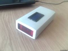
Unfortunately, there is no live board of the first prototype left :(. It was a board without amplification of the signal from the photodetector. The signal went directly to the MK.
The board looked like this:


Since the signal level from the photodetector was not always enough for the microcontroller, it was necessary to supplement the circuit. I built an amplifier using LM358. Now the circuit looks exactly as it does.
Having selected the case and adapted the board to it, this nice device was assembled:


The operating principle is as follows:
A mark is applied to the object under study using a regular office proofreader. About 5-7 mm in diameter. Or a white paper label is glued on.
When the power is turned on for the first time, the PIC begins to count the duration of the period between pulses, which, reflected from the tag, arrive at the photodetector . If there are no pulses for approximately 4 seconds, the reading is reset to zero. If there are no pulses for approximately 20 seconds, the device goes into low consumption mode. The indicator turns off. For the next measurement you need to press the button connected to port RB0. and the device “wakes up”. The cycle begins again.
The accuracy of the readings is excellent, but not over the entire range. At high speeds the readings “float”, but only slightly and not critically.
The only disadvantage of this device is its not very long range. About a centimeter. But this can be solved, as I wrote above, using a photodetector like TSOP1736 or TSOP1738 and a generator on a 555 timer. In this case, there is no need for LM358.
Another clarification is that the material of the object being studied must be dark.
The archive with the proteus file and the source is here.
By the way, I found an old source code that implements the principle of counting pulses using a capture module, but the indicator is LED. But it’s not difficult to remake it for LCD, it will be easier
This tachometer circuit on a microcontroller serves to measure the number of revolutions of virtually any internal combustion engine. The indication is made on a four-digit LED indicator, the measurement accuracy is 50 rpm.
Description of the tachometer operation on the PIC16F628 microcontroller
After applying the supply voltage, the digital tachometer immediately begins to verify the number of revolutions. The “SELECT” button selects one of nine speed measurement modes, depending on the type of vehicle sensor.
The first press of “SELECT” will display the current value of the number of pulses that the sensor produces per revolution of the flywheel. Initially set to 2 pulses per revolution. Accordingly, the indicator will display P-2.0. Each subsequent press of “SELECT” will cycle through all available values (0.5; 1; 2; 3; 4; 5; 6; 7; 8 pulses/revolution)

Upon completion of the selection of the required pulse value, after approximately 5 seconds the tachometer will remember it in the memory of the PIC16F628 microcontroller and enter the operating mode for measuring revolutions. The next time you turn on the tachometer, it is no longer necessary to set the pulses again.
For accurate operation of the digital tachometer, it is necessary to pay attention to the design of the input circuit. For each individual ignition system (depending on the car brand), it may be necessary to adjust the ratings so that the tachometer does not react to higher harmonics, and reacts firmly to the main one.
In the updated firmware version (tacho_univ_new), a 2-second indicator test function has been added to identify their possible malfunction.
A tachometer is a device that allows you to measure the rotational speed (rotation speed) of a mechanism (shaft, rotor, engine disk). The unit of measurement for rotation speed is usually revolutions per minute. The traditional method of measuring rotation speed is based on the implementation of speed feedback: a direct current generator is used, which is connected to the rotating mechanism in such a way that the voltage induced at the generator terminals is proportional to the speed of rotation of the shaft.
In this article we will look at the design of a tachometer based on a PIC microcontroller that does not have physical contact with the rotating part of the mechanism to measure its rotation speed. This technique is based on an optical method for determining the rotation speed, which requires the use of an infrared LED in conjunction with a photodiode.

The basis of the device in our case is a compact development board produced by the company.
The tachometer allows you to measure rotation speeds up to 99960 rpm with a resolution of 60 rpm. The result is displayed on a two-line LCD indicator.
The StartUSB for PIC debugging board is based on a Microchip microcontroller with support for the USB 2.0 interface. In addition, the board has contact pads with microcontroller input/output line signals, as well as an area for prototyping and connecting additional devices. USB data acquisition devices, communication devices and USB mp3 players can be developed on the basis of this board.

A distinctive feature of the StartUSB for PIC board is that the microcontroller installed on the board has a pre-installed USB bootloader, which eliminates the need to use an additional programmer. In addition, the company provides a free USB bootloader program for a personal computer, with which the user can easily program the microcontroller. A USB bootloader for the microcontroller (firmware) is also provided.
With the optical method of determining the rotation speed, an infrared LED transmits IR pulses, and a photodiode captures the reflected signal. If the surface of the rotating part is dark and rough, the reflected signal will be negligible, so we use a piece of white paper pasted on the rotating part. If the entire surface of the part is bright and reflective, then you need to use a piece of dark paper so that part of the IR radiation is absorbed during a full revolution. In any case, we will receive a pulse at the output of the signal conversion and matching circuit for each full revolution of the rotating part.
Schematic diagram of the IR sensor and signal matching circuit from the photodiode

The diagram shows that if a high level appears at the IR Tx pin, the transistor (npn) that controls the IR LED will open. The reflected signal enters the photodiode in the signal conversion and matching circuit; normalized pulses for counting by the microcontroller are taken from the transient collector (pnp). Under normal conditions, the photodiode resistance is high and the transistor is always off. The output of the circuit (transistor collector) is pulled to ground. If the reflected IR signal falls on the photodiode, its resistance decreases and the transistor opens, therefore a high level appears at the output.
In we will look at connecting the sensor and LCD indicator to the microcontroller, the main points in the configuration of the built-in timer of the microcontroller to solve our problem, as well as the design of the tachometer.
What is it anyway tachometer? A tachometer is a device used to measure the RPM (revolutions per minute) of any rotating body. Tachometers are made on the basis of contact or non-contact ones. Non-contact optical tachometers typically use a laser or infrared beam to monitor the rotation of any body. This is done by calculating the time taken for one rotation. In this material, taken from an English site, we will show you how to make a portable digital optical tachometer using Arduino Uno. Let's consider an extended version of the device with an LCD display and a modified code.
Tachometer circuit on a microcontroller
Schematic parts list
- Microcircuit - Arduino
- Resistors - 33k, 270 ohm, 10k potentiometer
- LED element - blue
- IR LED and Photodiode
- 16 x 2 LCD screen
- 74HC595 shift register
Here, instead of a slot sensor, an optical one is used - reflection of the beam. This way they don't have to worry about the thickness of the rotor, the number of blades won't change the reading, and it can read the drum revolutions - which the slot sensor cannot.

So first of all you will need an IR emitting LED and a photodiode for the sensor. How to assemble it is shown in step-by-step instructions. Click on the photo to enlarge the size.
- 1. First you need to sand the LED and photodiode to make them flat.
- 2. Then fold the strip of paper sheet as shown in the picture. Make two such structures so that the LED and photodiode fit tightly into it. Connect them together with glue and paint them black.
- 3. Insert LED and photodiode.
- 4. Glue them together with superglue and solder the wires.

Resistor values may vary depending on which photodiode you are using. The potentiometer helps to reduce or increase the sensitivity of the sensor. Solder the sensor wires as shown in the figure.

The tachometer circuit uses a 74HC595 8-bit shift register with a 16x2 LCD display. Make a small hole in the housing to fix the LED indicator.

Solder a 270 ohm resistor onto the LED and insert it into pin 12 of the Arduino. The sensor is inserted into a cubic tube to give additional mechanical strength.

That's it, the device is ready for calibration and programming. You can download the program from this link.
Video of a homemade tachometer working
|
|
 High voltage security device - electric hedgehog. Today we will continue our conversations about the structures that are needed to protect our home. The device that we will now consider is intended for protecting an apartment, office, cottage and car. The device is called a high-voltage electric hedgehog!
This digital tachometer is suitable for counting the revolutions of almost any type of internal combustion engine. The tachometer measurement error is only 50 revolutions/minute. A four-digit LED display is used to display the result.
To configure the operating mode, you must use the “Select” button. The first press displays the current operating mode on the display. The default operating mode is the third, when the sensor produces two pulses per revolution of the flywheel. Accordingly, the inscription P-2.0 will appear on the display.
Each subsequent press of the button switches the tachometer operating mode to the next one. There are nine of them in total: 0.5, 1, 2, 3, 4, 5, 6, 7, 8 pulses/revolution, respectively, they set the number of pulses issued by the sensor per one revolution of the flywheel. The higher the number of pulses, the more accurate the measurement.
After selecting the operating mode, you must wait 5-10 seconds. During this time, the tachometer will record the operating mode into the microcontroller’s memory and enter operating mode. In the future, the tachometer will immediately switch to operating mode when power is applied. If there is a need to reconfigure the tachometer, then you need to press the “Select” button and configure the tachometer again.
It is worth paying attention to the parameters and design of the input circuit. For a specific type of ignition, some adjustments to the ratings are possible, due to different ignition devices in different types of cars. This is necessary so that the tachometer works well with fundamental harmonics and does not react to higher harmonics. Without such adjustment, accurate operation of the tachometer is impossible.
The updated firmware version includes a function for checking indicators. This is necessary to conduct a two-second test to identify sensor faults.
Attached files:
Firmware –
Simple monoblock car amplifier based on TDA1560Q  Automotive throttleless power supply based on IRS2153 for laptops and mobile phones External USB connector in car radio